PalmSHIELD
Product Engineering
PalmSHIELD Elite Product Engineering
Executive Summary of T-Post Fence Engineering Summary
The three T-Post Fence Engineering Summaries follow a standardized 7-part structure but contain critical variations in design specifications that directly impact performance capabilities. The documents demonstrate a systematic approach to structural engineering documentation while accommodating different wind load and design requirements.
Document Structure Analysis
Consistent Framework (All 3 Documents)
All summaries maintain identical structural organization:
- Introduction – Company positioning and compliance statement
- Part 1 – Preparation – Engineering firm credentials and licensing
- Part 2 – Design Criteria – Wind load parameters and factors
- Part 3 – Materials – Aluminum specifications for components
- Part 4 – Design Criteria – Critical design characteristics
- Part 5 – Engineering – Span data and technical drawings
- Part 6 – Engineering Disclaimer – Liability and site-specific recommendations
- Part 7 – Engineer Stamp – Professional seal validation
Professional Engineering Standards
Each document includes proper engineering authentication:
- Licensed Professional Engineer
- Official engineering firm (Rise Structural Associates)
- Professional stamp and date
- Clear disclaimer regarding site-specific requirements
Critical Technical Variations
Wind Speed Requirements
- Document 1: 120 mph wind speed
- Documents 2 & 3: 150 mph wind speed
Panel Support Spacing (Most Critical Difference)
- Document 1: 42″ on-center maximum spacing
- Document 2: 32″ on-center maximum spacing
- Document 3: 26″ on-center maximum spacing
Louver Specifications
- Documents 1 & 3: Solid louvers with no penetration
- Document 2: 20% open area (5″ spacing, 1″ openings)
Corresponding Span Capabilities
10-foot Height Panels:
- Document 1: 42″ span width
- Document 2: 32″ span width
- Document 3: 26″ span width
8-foot Height Panels:
- Document 1: 60″ span width
- Document 2: 60″ span width
- Document 3: 52″ span width
Structural Logic and Performance Relationship
The documents demonstrate clear engineering logic where increased wind loads require more restrictive support spacing:
120 mph wind (Document 1) allows maximum flexibility with 42″ spacing
150 mph wind with openings (Document 2) requires 32″ spacing due to aerodynamic considerations
150 mph wind with solid panels (Document 3) demands most restrictive 26″ spacing due to maximum wind resistance
Wind Load Requirements
Today’s architectural community is now giving consideration beyond the building to meeting wind load requirements. Architects and engineers are viewing the entire site and site amenities for compliance with the American Society of Civil Engineers wind load requirements. Safety is our highest priority. Safety must also include assuring non-habitable structures are secure and not posing a safety risk to habitants during these wind events.
Once designers have met all obligations to providing safe structures; these planners are now giving consideration to assuring all site amenities outside the building are designed to mitigate any preventable damage, causing considerable construction expense to property owners and unsightly outcomes for tenants.
Most PalmSHIELD systems are designed to meet 120 mph rating. Please request 150 mph rating at time of quotation. PalmSHIELD does not guarantee wind load rating unless specifically requested and stated by PalmSHIELD per our quotation and fabrication documents
Structurally Sound
PalmSHIELD has been working with engineers for over twenty years in assuring that our architectural screen fencing and wall, louvered mechanical equipment screen and rooftop screen fencing are structurally sound and do not interfere with the mechanical performance of the equipment they were intended to screen. Mechanical equipment may include compressors, condensers, chillers, rooftops, HVAC, compactors, breakers, meters, containers, generators, and like-kind equipment. Each one of these unique pieces of equipment has recruitments specific to the volume of air surrounding the equipment and the exchanging of that air which allows for dispersing heat.

Anchoring
Mounting Options
It is up to the owner or project engineer to select the type of anchoring system for anchoring PalmSHIELD’s plated column design to your structure. We have worked with engineers across the United States to attach the PalmSHIELD architectural screen fencing and wall product to structural steel and adjoining structures for rooftop installations. However, the majority of our installations are mounted to the top of concrete surfaces.
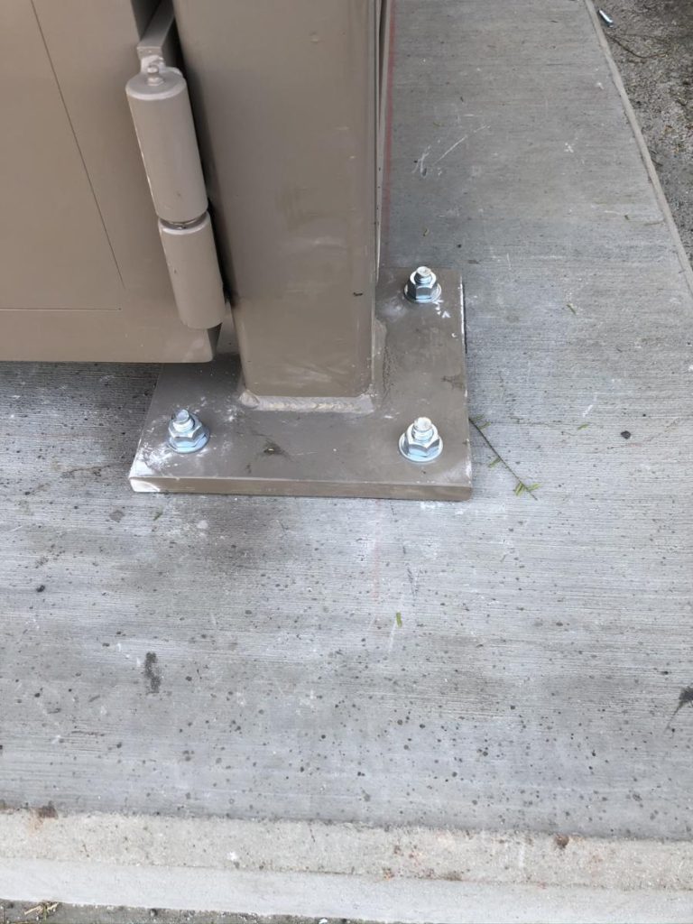
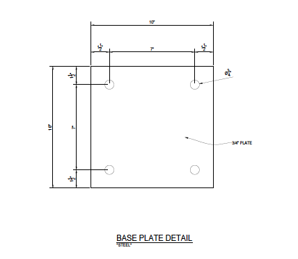
Base Plate Details
PalmSHIELD uses a very wide ¾” base plate design that is gusseted to the posts and welded in accordance with AWS D1.2 requirements and related certification. This large plate design is intentional to allow the customer to use a wide variety of anchoring options. The use of this large plate spaces the anchor holes more than 7 inches apart. By spacing the anchors this distance, it prevents overlapping of the tension placed on the concrete by each anchor.
Anchor Engineering Considerations
When installed, concrete anchors place tension against the adjoining concrete under a load. The tension begins to diminish the farther away you get from the center of the anchor. Assuming you have adequate concrete of at least 4000 psi, the load can be predicted by the anchor manufacture relative to the area of concrete impacted by this tension. If concrete anchors are installed too close to one another, this loading is overlapped and increased exponentially thus potentially causing the concrete to fail or sprawl. Consideration should also be given to how far the anchor is installed relative to the edge of the concrete. If there is not enough concrete from the center of the anchor to the edge of the concrete to absorb the tension of the anchor under a load, the concrete may fail. Anchor manufactures call this area around an anchor a sprawl cone with the larger end of the cone closer to the top of the anchor. When two anchors overlap or the cone reaches to the edge of the concrete, there is concern that the anchor may fail.
PalmSHIELD is not recommending any anchor, anchor spacing, depth or edge spacing. We are simply offering some solid advise to our customers that these are important considerations that should be properly engineered. If notified at time of quote request and provided with the site specific engineering requirements, PalmSHIELD can provide you with engineering that will determine your specific anchoring requirements during the submittal process. On a site specific basis, PalmSHIELD can offer jurisdiction specific engineering working with engineers who are certified in that jurisdiction. As our PalmSHIELD product has been stamped for approval in multiple installations, we work seamlessly with engineers to meet your requirements.
PalmSHIELD Elite Panel Rooftop Screen Rail Structural Calculation
PalmSHIELD’s A1000 Equipment Rail is designed giving consideration to meeting structural performance, a wide variety of roof tops, easily sealed to prevent roof leaks and custom patterns for attachment.
- The primary trapezoidal rail is constructed of 8” x 2” x ¼” structural aluminum channel. Being purposeful in choosing this profile, PalmSHIELD wanted to be sure we selected a large enough profile to meet almost any screen height and wind load requirement. This wide profile was also selected for its ability to customize the pattern for attachment to a wide variety of roof types. Metal standing seam roofs require roof rails to be attached to underlying roof beam, purlins and bar joists. The location of these structural members do not always line-up with rooftop screening rails so PalmSHIELD uses this wide continuous profile for the end user to custom design where the anchoring will occur to capture the roof structural members.
- Each roof rail is custom designed to meet roof slopes and changes in elevation. End users and designers provide PalmSHIELD with roof slopes and changes in roof elevations and PalmSHIELD provides detailed fabrication drawings showing each roof rail with its unique slope and elevation. PalmSHIELD recognizes that not all roofs are the same and customization is necessary without compromising structural requirements.
- Roof rail lengths are customizable to meet roof structural members and improved structural performance. Each rail includes a 45 degree brace that extends from the base of the rail to the equipment screening column. This bracing significantly improves performance and reliability.
- All roof rails are designed to work with PalmSHIELD screening plated columns. The top of the roof rail will marry-up with the column hole pattern, making attaching columns easy and performed mechanically in the field. All points of attachment are easily accessible and no disassembly of the rail is required.
- Roof rails lower rail sits flush on top of the roof. It accommodates U-bolt, epoxy anchor or mechanical anchor attachment to the roof. With a considerable surface area, the rail will not damage TPO, EPDM, PVC, Asphalt and coated roofs. Sealant may be placed under the lower rail, around anchors and along the entire edge of the rail.
PalmSHIELD’s A1000 Equipment Rail is engineered for 120 mph wind speeds at eight foot tall and rails on five foot centers assuming the screening is solid. This is the basis of our engineering. If additional site conditions are warranted beyond these conditions, PalmSHIELD will work with our engineers and local site engineers to meet these conditions. We are subject matter experts and understand how to design our equipment rails to meet these conditions.